Download this article in PDF format.
It’s normal to assume that there’s an easy way to relate the bandwidth of a power-supply control loop to its transient response—no good reference exists that defines this in simple terms. It seems like a straightforward problem, which should have a simple solution. The higher the bandwidth, the faster the loop responds, and with less voltage deviation.
However, several limiting factors may get in the way of this simple relationship. The first one is the series resistance of the output capacitor. If that resistance is too high, then the load step creates a large voltage deviation before the control loop can respond. Equation 1 gives the peak voltage deviation:
Second, the inductor can cause slew-rate limiting. This is related to the control-loop bandwidth by the voltage across the inductor, calculated with Equation 2:
Third, there’s a critical inductance limit beyond which the duty cycle will saturate. The peak transient voltage is then determined by the large-signal limiting of the inductor current into the output capacitor. This is related to the voltage across the inductor, output capacitor, and series resistance, as expressed by Equation 3:
Look at the design of power supply intended to avoid these issues, and use an electronic load to test the transient response. If your control-loop bandwidth is relatively high, the output voltage may follow the load current and isn’t limited by the control loop. In this case, you can use a MOSFET and load resistor on a small board for the load step, controlled by a function generator. A low duty cycle for the load on-time will minimize dissipation in the resistor.
1. This typical power-supply test setup is used for fast load-transient testing; short leads with low inductance are essential for valid measurements.
It’s important to mount this as close to the power-supply output as possible in order to minimize wiring inductance;Figure 1shows a typical setup. The small black wire connects to a surface-mount coaxial cable for the output-voltage measurement.
2. The measured transient response shows tP= 25 μs and VP= 130 mV for a current load step of ∆I = 5 A.
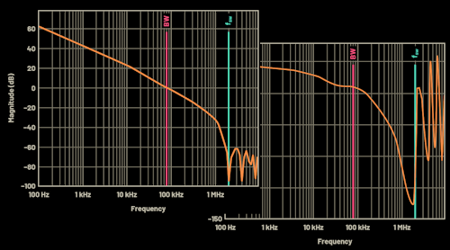
Figure 2shows the measured transient response, which is directly related to the bandwidth of the control loop ofFigure 3. With no equivalent series resistance (ESR), or slew-rate or duty-cycle limiting, the initial response time is one-fourth the effective control-loop period. This is the equivalent first quarter of a sinusoidal response at the unity-gain frequency. The peak voltage will vary based on the topology and damping, but is easily predictable with a surprising degree of accuracy.
3. The corresponding control-loop bandwidth for the system with transient response is 10 kHz.
With no ESR, slew rate or duty-cycle limiting, Equation 4 calculatestPas:
For current-mode control, Equation 5 gives the single-pole approximation that results in the peak voltage deviation:
Equation 6 calculates the critically damped case for current-mode control (as shown in Fig. 2):
For voltage-mode control, Equation 7 gives the peak voltage deviation:
It’s important to verify the performance over all operating conditions. Duty-cycle limiting can cause a significant droop when operating the control loop outside its linear range(Fig. 4).
4. Output voltage is compared with different input voltages at a 5-A load step; significant output-voltage droop can occur when the control loop is operating outside its linear range.
From this, we see that the relationship between bandwidth and transient response is simple and straightforward. By observing the transient response, you can quickly get a good estimate of the control-loop bandwidth.