
|
|
Download this article in .PDF format This file type includes high resolution graphics and schematics when applicable. |
Author’s note: Early in my engineering career, I accepted a research project to characterize light transmission behavior through D-type optical fiber while the fibers bathed in an acid bath for multiple hours. I was happy to see a new scope that wasn’t being used and commandeered it for my work. Not having previously written software to control and analyze scope measurements, I immediately went to work on the new oscilloscope. After two weeks of developing test fixtures and writing software, I began to run into unexpected issues while running my first tests. New to this type of work, I asked for assistance from an experienced engineer. “Why in the world are you using a sampling scope for this experiment?” he asked. The question caught me by surprise. I began wondering what the difference was between a sampling scope and a real-time scope, what applications each one serves, and where they overlap.
Real-time oscilloscopes are now commonly called digital storage oscilloscopes (DSOs) or mixed-signal oscilloscopes (MSOs). Most oscilloscopes sold today are real-time scopes. Real-time scopes come in bandwidths that range from a few megahertz to tens of gigahertz, and they can be purchased for as little as a few hundred dollars or as much as a few hundred thousand dollars.
Sampling scopes, commonly known as digital communication analyzers (DCAs), typically start in bandwidths of tens of gigahertz and are used primarily for analyzing high-speed serial buses, optical devices, and clock signals. As bandwidths continue to increase, however, sampling scopes and real-time oscilloscopes have begun to overlap in numerous application spaces.
The path to digitalization for both real-time and sampling scopes is essentially the same. The input signal passes through front-end signal conditioning circuitry on the oscilloscope and is digitized, stored to memory, and then displayed on screen. However, the underlying technology for each varies dramatically.
Table Of Contents
• Real-Time Scopes
• Sampling Scopes
• Sampling Vs. Real-Time Oscilloscopes
• Noise And Signal-To-Noise Ratio
• Frequency Response
• When To Use A Sampling Scope Or A Real-Time Scope
• Conclusion
Real-Time Scopes
How do real-time scopes work? Real-time oscilloscopes include trigger ASICs that allow users to specify specific events of interest, such as a rising voltage threshold, a setup and hold violation, or a pattern trigger. In their normal acquisition mode, when the scope trigger circuitry sees this event, the scope will then capture and store contiguous sample points around this trigger point and update the display with the captured data.
Real-time scopes can be run in single-shot mode or in repetitive or run mode. In single-shot mode, the scope acquires and displays a single acquisition of consecutive samples determined by the memory depth and sample rate set on the oscilloscope. The user can pan and zoom to any event of interest in the scope acquisition after the scope captures a single trace. In run mode, the scope continues to acquire and display each condition that matches the scope’s trigger specification. Variable or infinite persistence enables successive signal captures to be overlaid on the original signal. Repetitive mode is commonly used since it provides a live view of the device under test (DUT). Measurements like rise time or pulse width and analysis such as math or fast Fourier transforms (FFTs) can be performed in either single-shot mode or over a period of repetitive acquisitions.
Real-time oscilloscopes are defined by three key banner specifications, namely bandwidth, sample rate, and memory depth. Of course, there are many more important specifications that must be considered when looking at a real-time oscilloscope. Most real-time scopes below 6-GHz bandwidth include both 1-MΩ and 50-MΩ inputs, which enables them to be used with a wider variety of probes and cables not compatible with sampling scopes.
Sampling Scopes
Sampling scopes are uniquely designed to capture, display, and analyze repetitive signals. Triggering capabilities are likewise crafted for repetitive signals. A sampling scope will capture a set of non-contiguous samples spaced in time when it sees its first trigger condition. The scope delays the trigger point, captures the next set of points, and places them on its display with the first set of points. It repeats this process, building up the waveform in an infinite-persistent mode over successive acquisitions.
一个关键的技术组件(触发插值)控制触发器之间的时间分辨率以进行测量精度。内存深度不是关键规范,也不需要,因为在每个触发器上仅捕获并处理几个点。同样,样本率也不关键。相反,从第一个触发条件到下一个触发条件从第一个触发条件稍微延迟至关重要。
Sampling Vs. Real-Time Oscilloscopes
如前所述,实时示波器的带宽现在超过60 GHz,现在采样示波器现在达到90 GHz。结果,对于大多数数字应用程序,带宽不再是确定哪个是正确选择的示波器的简单标准。话虽如此,价格仍然是一个关键区别。50 GHz的满载示波器的示波器的成本将低于150,000美元,实时示波器接近$ 400,000 USD。设计师必须选择实时示波器的灵活性是否值得增加成本。
Noise And Signal-to-Noise Ratio
There are a lot more differences between a sampling scope and a real-time oscilloscope. A sampling oscilloscope has a 14-bit analog-to-digital converter (ADC). Consequently, it has a very large dynamic range, which enables it to look at signals ranging from a few millivolts to a full volt without the need of attenuation. The sampling scope, then, maintains very low noise at different volts per division settings. The real-time oscilloscope is limited in its dynamic range to 8 bits, but typically will show an effective bit number of around 6 bits.
As a result of the limited signal-to-noise ratio (SNR), it must use attenuators to correctly display signals from a few millivolts to several volts. Ultimately, this means that a real-time oscilloscope will have higher noise than a sampling oscilloscope. The low noise of the sampling oscilloscope has led it to be considered the “gold standard” of measurements, but real-time oscilloscopes continue to improve and have begun to narrow the signal integrity gap.
Frequency Response
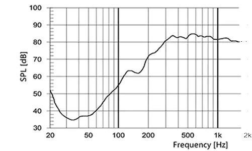
Another consideration when choosing between a real-time oscilloscope and a sampling oscilloscope is their frequency response. A sampling oscilloscope typically won’t use digital signal processing (DSP) correction, so it has a frequency response that rolls off slowly (its hardware response) and looks more Gaussian in shape. A real-time oscilloscope can implement DSP and thus can correct for its frequency response. For instance, Agilent’s DSOX93304Q uses a flat frequency response through its entire passband, which means that its gain will not vary by more than 1 dB in the entire frequency of the scope.
Frequency responses on real-time oscilloscopes can vary. Some oscilloscope vendors have up to five responses that all have different characteristics. During side-by-side comparisons, the flat response and the Gaussian response make two measurements look tremendously different. For instance, a Gaussian roll-off can influence a measurement and add intersymbol interference. A flat response that rolls off quickly can exhibit what looks like ringing in its response if a signal is fast enough to drive past the oscilloscope’s bandwidth. In either case, one must understand how the hardware can influence measurements.
Clock Recovery Differences
Clock recovery is a key component of oscilloscope measurements. Recovering clocks allows for building of a real-time eye, mask testing, and jitter separation. Essentially a recovered clock is a reference clock used for measurement comparisons. Until recently, sampling oscilloscopes relied entirely on hardware to recover a clock. As a result, whether the clock was an explicit clock or an internal 10-MHz clock provided by the sampling scope itself, the recovery system was prone to error.
不再是这样。例如,敏捷nt sampling scope now can provide a software-based clock recovery system, which is ideal for making accurate clock recoveries. The real-time oscilloscopes almost always will use a software clock recovery. However, it does have the added feature of using explicit clocking. Again, the advantage of a software clock recovery is that it is not prone to the hardware errors, but will land its edges where they need to be regardless of data rate.
In addition to the difference between a hardware clock recovery and a software clock recovery, one must pay attention to the clock recovery algorithm that is being used. Sampling scopes typically will use a jitter transfer function (JTF), where real-time oscilloscopes will use an observed JTF (OJTF). The OJTF will cut off more low-frequency jitter than a JTF. As a result, you could see significantly lower jitter numbers on the real-time scope than the sampling scope. Thanks to recent advances in sampling scopes, users can reset the numbers simply by changing both scopes to the same transfer function, making jitter comparisons significantly easier.
When To Use A Sampling Scope Or A Real-Time Scope
从历史上看,在最大带宽和内在的抖动中,采样示波器比实时示波器具有优势。然而,在过去的十年中,实时示波器已大大缩小了差距,为参与收发器测试的用户提供了选择是使用实时范围还是采样范围的选择。不过,采样范围仍然具有较低的抖动和更高的动态范围,因此它非常适合在受控环境中进行表征。假设您的信号是可重复的,或者可以用实时眼睛捕获,则采样范围将为您的信号提供真实的描述。
Flexibility makes real-time scopes appealing. If the user is debugging and wants to trigger on difficult to find events, the real-time scope is ideal. Real-time scope users can choose from a myriad of compliance, protocol triggering and decode, and analysis applications. The real-time scope also can measure jitter on single acquisitions, making it very good for analyzing root causes of failures. Most methods of implementations in standards use real-time scopes for transmitter testing as well, which means users may need to use a real-time scope to ensure that their devices are “compliant.”
Conclusion
For most scope applications, real-time scopes provide a great fit. They come in a variety of bandwidths, include the ability to capture single-shot events as well as repetitive signals, and have narrowed the gap for high-frequency measurements such as jitter and transmitter characterization.
If your application includes a repetitive waveform that requires lower jitter and a higher dynamic range, a sampling scope is a good choice. Sampling scopes also have the advantage of a lower initial cost and modular upgrades, making them well suited for electrical and optical manufacturing test applications.
If you’re working at frequencies greater than 20 GHz and are unsure of which type of scope to choose, engage with a scope vendor that carries both sampling and real-time scopes. The vendor will have a mutual interest of ensuring that the scope you choose matches your needs, unlike a vendor that only carries real-time scopes or has a limited offering of sampling scopes.