Conformance tests are performed on serial data interfaces such as USB, HDMI and PCI Express to ensure interoperability between electronic devices and accessories. In cases where signal integrity problems are encountered, modern oscilloscopes support root cause analysis by providing powerful tools such as eye diagrams, jitter and noise separation as well as time domain reflectometry.
Automatic conformance tests for high speed data interfaces
一致性测试代表了产品开发过程中一个重要的里程碑。相关的标准化委员会已针对USB和以太网等许多接口发布了详细的测试规范。专业测试实验室为此类接口提供完整的测试服务,包括文档和认证。对于需要自己执行这些测试的用户,现代的高性能示波器为所有常见的接口标准提供了自动测试解决方案。这些解决方案配备了图形测量配置工具和外部测试序列。无论如何执行测试:如果结果不符合标准,则需要耗时的调试。
在根本原因分析期间,示波器为分析工具提供支持,例如带掩模测试的眼图或抖动和噪声组件的分离。时间域反射仪也可用于验证被动信号路径组件的传输特性,例如连接器,电缆和印刷板上的信号线。
USB 3.2发射器的一致性测试
USB 3.2发射器符合测试的重点是眼图(发射眼),用于验证眼睛张开,信号水平和抖动组件。该测试直接在设备输出(短通道)以及模拟信号路径(长通道)上执行。对于长频道测试,USB实施程序论坛(USB-IF)已发布了带有S-Parameters的文件,用于各种电缆和信号跟踪长度。在测试过程中,示波器以200 µs的长度获得时钟和数据信号序列。然后,使用SigTest USB-IF分析软件检查这些序列是否符合标准。根据测试模式,每个USB设备必须自行生成合规模式:对于USB 3.2 Gen 1,这意味着模式CP0(数据)和CP1(时钟)(时钟)以及USB 3.2 Gen 2,模式CP9(数据)和CP10(钟)。切换到下一个CP模式涉及将简短的LFPS序列发送到USB设备中的接收器。
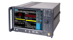
The R&S RTP oscilloscope from Rohde & Schwarz for example supports conformance testing for USB 3.2 Gen 1 (13 GHz model required) and for Gen 2 (16 GHz model) (Fig. 1). The SigTest analysis software is integrated into the USB 3.2 conformance testing option, and the corresponding test sequence is automated. The option provides convenient graphical support to guide the user through the measurement. With the integrated two-channel 100 MHz generator option, switching between the individual test patterns takes place automatically. Simultaneous testing of the short and long channels is another simplification. The trace from the short channel setup is processed using embedding filters generated on the basis of USB-IF S-parameter files to produce a long channel trace (Fig. 2). Complete test results are compiled in a detailed report.
USB 3.2 device error example
Fig. 3 shows an example of errors that occurred during the transmitted eye test for a USB 3.2 Gen 1 device. The random jitter (RJ) determined with the clock pattern (CP1) is especially noticeable. The corresponding eye diagram for the data pattern (CP0) also exhibits high jitter and noise. The analysis tools provided with the R&S RTP make it possible to investigate the root causes of these problems.
用眼睛的快速概述
Eye pattern analysis is one of the best-known techniques for performing fast signal integrity tests. It involves superimposing the individual data bits of a signal sequence (Fig. 4). Selection of the appropriate timebase for bit analysis is critical here. For all USB standard generations, 2nd order clock data recovery (CDR) is defined with different transfer functions.
USB标准中指定的眼膜具有六边形形状(图5)。对于Gen 2的Gen 1和70 mV的值指定了目击的最小高度。最小的眼睛宽度等于位长度(单位间隔,UI)减去最大总抖动(TJ)定义为10–12的位错误率。对于USB 3.2 Gen 1,该值为68 PS,对于Gen 2,为28.6 PS。
的r和s RTP装备生成眼图with a configurable CDR that is implemented in the hardware and can be used as a trigger. A continuously running CDR enables a large observation interval for the signal stream that allows detection of sporadic errors. The mask can be configured in the eye center so that acquisition is stopped when a mask violation occurs.
图6显示了上面提到的故障USB 3.2 Gen 1设备的眼睛测试。正如在符合测试中已经检测到的那样,眼图显示出高抖动和噪声组件。眼睛右侧的附加直方图阐明了位边缘的时间分布,从而阐明了抖动。双峰直方图格式揭示了一些其他信息:信号中还包含高确定性抖动。
由于抖动和噪声组件而解决的错误来源
眼图中的直方图可以提供对抖动和测试信号中包含的噪声的初始见解。但是,为了获得有关干扰源的更多详细信息,将总抖动和总噪声分解为单个组件非常有帮助(图7)。
For example, high random jitter (RJ) or high random noise (RN) can be a sign of problems in the semiconductor itself (thermal noise, shot noise) or an unstable clock oscillator. Deterministic periodic jitter (PJ) components can arise, for example, due to an unstable PLL or interference from switching power supplies. Data dependent jitter (DDJ) components are divided into duty cycle distortion (DCD), e.g. due to asymmetrical signal edges and intersymbol interference (ISI). The latter can be caused, for example, by transmission losses due to low bandwidth of signal traces or by reflections on vias or connectors.
Once the jitter separation is completed, detailed results are available (Fig. 8). The results table (top right) shows that the periodic jitter (PJ) dominates the deterministic jitter. The random jitter (RJ + (O)BUJ) is also noticeably high. The PJ histogram has a distribution that suggests sinusoidal interference. The second table (bottom right) lists the estimated periodic jitter components. Here, high jitter values are noticeable at 100 MHz. This is generally valuable information since the interference frequencies can be tracked back to the corresponding function blocks. Appropriate measures can then be taken to reduce the interference coupling. The power supply is a typical weak point. Interfering signals are easily injected via the supply lines and ground planes. In this example, the generator option of the oscilloscope was connected to the 5 V supply voltage of the USB device under test. The injected generator signal caused the periodic interference at 100 MHz, while the additional noise resulted in strong random jitter (Fig. 9). Comparison with the situation after switching off the interference source makes this clear (Fig. 10). Once the interfering signal is eliminated, the jitter measurement included in the conformance test passes with no problems.
Testing the signal path with TDR
In addition to analyzing the active signals, it is also important to check the signal paths in case of signal integrity problems. Here, the focus is on the transmission losses as well as the impedance response and stability along the signal path. Depending on the signal, the bandwidth of the signal paths on the printed board, the connectors, the cables, etc. requires appropriate design and selection. Impedance steps should also be avoided due to the reflections they can cause.
The relevant measurements are usually performed using network analyzers. The R&S RTP with integrated time domain reflectometry (TDR) provides a useful alternative. The differential 16 GHz pulse source is used as a stimulus; its reference outputs allow measurement of the reflected signals with the oscilloscope channels.
The application software provides support during setup calibration as well as during the measurement. TDR can be used to measure the impedance and reflection coefficient along the signal path.
Fig. 11 shows measurement of a USB test fixture. The differential pulse source was connected to the SMA connectors. The USB type A connector was left open so the supplied signal pulse would be fully reflected. The impedance and the reflection coefficient can be displayed vs. time as well as vs. distance, allowing easy correlation to local sections of the device under test. We can clearly see the impedance step at the transition from the SMA connectors to the printed board, the constant impedance along the signal trace, and the reflection at the USB connector.
Time domain transmissometry (TDT) is another useful measurement capability. Here, a fast pulse is also fed into the signal path. The output is connected to the oscilloscope channel to allow determination of the transmission losses. The TDT result shows the pulse shape that arises due to transmission losses. The rise time measured in the example in Fig. 12 suggests a bandwidth of about 3.2 GHz (BW = 0.35/trise).
概括
在确保电子设备及其配件之间的互操作性方面,串行总线接口上的一致性测试包括重要的测量。遇到错误时,适当的T&M设备是快速确定根本原因的关键。除了执行自动符合测试的软件选项外,R&S RTP等现代高性能示波器还提供了许多非常有用的工具来调试信号完整性问题。
Guido Schulze, product manager oscilloscopes at Rohde & Schwarz, Munich