|
|
Download this article in .PDF format 此文件类型包括适用时的高分辨率图形和原理图。 |
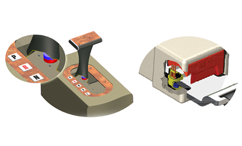
This 8051 microcontroller-based control circuit adjusts the speed of a small permanent-magnet dc motor via photosensors(see the figure)。该电路可以在光跟踪系统中找到应用,以根据入射光的强度调节跟踪电动机速度。也可以修改它同时控制多个电机。
根据连接到微控制器的两个光电传感器,电路和软件在三个级别中变化了三个级别的速度。微控制器输入端口(端口1)感测每个光电传感器电路的电压电平,而存储在微控制器的存储器中的程序在其输出端口(端口2)处产生必要的PWM信号以驱动电动机电路。
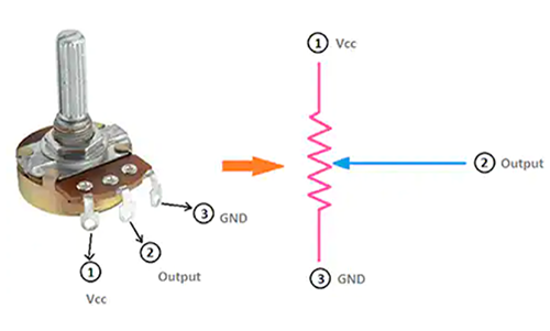
Motor speed can be adjusted by the light intensity falling into the photoresistors LDR1 and LDR2. These resistors control the bias points of two transistors connected via an input inverting buffer (74LS240) to Port 1 of the AT89C51. The base and collector resistors of the photosensor circuit were chosen empirically to properly set the transistor in cutoff and saturation regions. The output signal from Port 2 of the microcontroller is delivered to the motor circuit with the aid of a non-inverting buffer (74LS244).
当没有入射在任何一个LDR上时,其电阻大(达到约1mΩ),从而关闭晶体管。在这种情况下,该晶体管的集电极电压将是高(+ 5V)。另一方面,当光亮度在光致抗透光器上增加时,其电阻将在全光照照射下减小至约1kΩ,从而使NPN晶体管(2n2222)与其连接以接通。在这种情况下,晶体管的集电极电压将是低的。
The inverting buffer (74LS240) is used to invert the signal levels at the nodes of the transistors’ collectors. When either of the two transistors is on, the signal at the input of the respective buffer (A1 or A2) is at logic 0 (grounded), and in this case, the buffer output (YA1 or YA2) is high. On the other hand, when the transistors are off, the corresponding output of the buffer is low. This buffer is also used to protect Port 1 of the 8051 microcontroller.
74年ls244缓冲保护s Port 2 of the 8051 microcontroller from the motor circuit and provides sufficient current to drive the output transistor. The dc motor is connected to a +5-V dc supply via the driving transistor. And a free-wheeling diode is connected across the dc motor to protect the transistor from any back-induced voltage. The capacitor in the motor circuit removes the EMI and noise produced during motor operation.
When the output signal from pin P2.0 is set HIGH (Logic 1), current passes through the buffer and the base of the driving transistor. This turns on the driving transistor and the dc motor. The signal generated at pin P2.0 is a pulse-width-modulated waveform to control the average voltage provided to the motor, by controlling the switching-on time of the driving transistor. The control program stored in the memory of the 8051 microcontroller generates this signal.
The control program(见下面的列表)was converted into a hex machine-code file using the ASEM-51 assembler, and then burned into the flash memory of the AT89C51 using a commercial universal programmer. The selection of the required speed is achieved by controlling the light falling on LDR1 and LDR2(见表)。
Port 1 is defined as an input port, while Port 2 is left as an output port. The received signal from Port 1 is masked with the binary number 00000011 using the ANL logic instruction, to check the value received by Port 1 depending on the states of the photosensors. This value is compared with 00, 01, 02, and 03, respectively, to send the appropriate PWM signal into the motor circuit. A delay subroutine is included to produce the necessary delay times for the required PWM signals.
; DC MOTOR SPEED CONTROL ORG 00H MOV P1, #0FFH BEGIN: MOV A, P1 ANL A, #03 CJNE A, #00, SPEED1 CLR P2.0 SJMP BEGIN SPEED1: CJNE A, #01, SPEED2 SETB P2.0 ACALL DELAY CLR P2.0 ACALL DELAY ACALL DELAY ACALL DELAY SJMP BEGIN SPEED2: CJNE A, #02, SPEED3 SETB P2.0 ACALL DELAY ACALL DELAY CLR P2.0 ACALL DELAY ACALL DELAY SJMP BEGIN SPEED3: SETB P2.0 SJMP BEGIN DELAY: MOV R0, #0FFH H1: NOP DJNZ R0, H1 RET HERE: SJMP HERE END 

_pushing_performance_beyond_silicon.png?auto=format,compress&fit=crop&h=139&w=250&q=1)