
Memberscandownload this article in PDF format.
What you’ll learn:
- 为什么我们应该使用多相巴克转换器。
- How to use buck converters in parallel to increase the output current/power.
- How to derive the small-signal transfer function of a multiphase buck converter from a single-phase buck converter.
Automotive headlights don’t have to provide just a fixed beam when alternatives likeValeo’sPictureBeam Monolithic technology make it possible to control the intensity of light that’s projected very precisely. It allows the headlamps to automatically adjust the intensity of light to highlight road signs and other objects to gain the driver’s attention. Each pixel can be managed individually to adjust the light and flux accordingly. One challenge with this type of technology involves the precise control and powering of LEDs.
Converter Topologies: From LED Strings to Pixelated LEDs
在the latest LED drivers for automotive front lighting, you generally find buck converters with currents of up to 1.5 A to drive a single LED string. The buck converter acts like a current source for one single LED string(Fig. 1)。There are several buck converters that target different lighting functions.
Because the LED string voltages generally exceed the battery voltage VIN, you need a boost stage upstream. You will find this topology in all LED drivers for headlamps since they allow for the highest flexibility in LED count and LED current. The boost voltage, which is generally around 45 V, can supply up to 10 buck converters.
Multiphase Buck for Pixelated LEDs
For the pixelated LED, you now need a buck converter as a voltage source with an output voltage that’s slightly above the forward voltage of a single LED. Each LED has its own current control. The current seen by the buck converter, though, is much higher—it’s in the range of 10 A or more as you sum up some thousand paralleled LEDs or pixels(Fig. 2)。
在stead of designing a buck converter with a single coil in that range(Fig. 3), one possible solution is to use several buck phases.
As a result, we can benefit from the cost advantage of “high runner” coils and keep the reflow process for SMD instead of selective soldering of “pin through hole” components like big power coils.
Multiphase reduces ripple (current and voltage), and therefore reduces RMS currents in the input filter. The number of buck phases can be scaled to fit to the power needed by the application and allows for heat spreading over the available PCB area. Converter ICs exist with integrated switches, the feedback, and protection function and are ready to be used in multiphase systems.
在that case, one IC is the master (MS)(Fig. 4)。It ensures the closed loop and controls the slave (SL) by the control voltage VC, which sets the peak current of the coil current. Therefore, the master will set the same peak current for each phase. In practical implementations, the phases are shifted over time to avoid the switching of all phases at the same time.
Stability with Small-Signal Model
Stability must be studied for all types of closed-loop systems. Lots of literature exists on how to do this with a small-signal model of a buck converter.
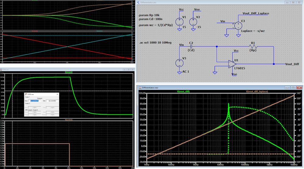
An alternative approach is to use powerful tools like SIMPLIS. It allows you to get the ac simulation, without the need to create a small circuit model of the converter. We can nearly draw the schematic as is and launch an ac simulation, ultimately obtaining the bode plot of the transfer function of the power stage (PS).
But, unlike a small-signal model, it’s difficult to understand where the poles and zeros originate. Many publications discuss different small-signal models, but only single-phase versions. This article treats the case of several phases by extending the existing small-signal model to multi-phase.
在our case of fixed-frequency current-mode control with the switching period TS, Raymond B. Ridley1developed the control-to-output function, which shows the relation between the control voltagevCSand the output voltagevO:
Figure 5is a graphical representation of the PS with its inductor, load, and capacitor. PS includes the current-sensing gainRifor the current control, the slope compensation by the external slopeSe, and the natural slopeSn。
Here, mcis defined asmc= 1 + (Se/Se) andD’= 1 –D, withDas the duty cycle of the converter.
The power stage also contains the “sampling” effect modeled byHe(s), created by the fact that the converter “samples” the inductor current with the switching frequencyfs。
As a result, the transfer function consists of:
- A first part, which is the dc gain.
- A second partFp(s)that contains the power stage at given output load and capacitor.
- A third partHe(s)that models the sampling effect.
We now add a second identical phase to analyze the impact on the system(Fig. 6)。负载和输出电容保持不变。If we want the same output voltage, this also means that the control voltage must be different. It’s now namedvcn。
Each phase of the converter now delivers half of the output current. Even if both power stages are identical toFigure 5, their small-signal model is not, as each sees only half the output current. That’s why they are labeled PS’(s).
Figure 6can be drawn differently by splitting the load without changing anything for each phase of the converter. Each phase still delivers half of the output current at the output voltagevO(Fig. 7)。
We can now apply Ridley's control-to-output function and extend from 2 tonphases and replaceRwithnR,CwithC/n, andRCwithnRC。
The static gain is modified withRreplaced withnR, therefore:
The transfer function FP(s) is impacted; even if in the numerator n cancels out, the poleωpis affected:
Hp(s)isn’t affected—it depends only on the switching frequency.
So, we now have deduced the new control-to-output function when parallelingnphases:
Checking with SIMPLIS
We can do some checks by comparing the control-to-output transfer function with the SIMPLIS model and sweeping some parameters, for instance the output currentIO。
We sweep from 1 to 10 A, which means that we changeRin the transfer function. As expected, this influences the dc gain and the pole ofFP(s)(Fig. 8)。The dc gain drops from 27 dB to 14 dB and the pole moved from 800 Hz to 3.3 kHz. Obviously, the small-signal and SIMPLIS transfer functions perfectly match up to half the switching frequency.
The fact that, for frequencies above half the switching frequency, both models don’t match anymore is due to the simplified modelization of the sampling effect byHe(s)。As detailed in Ridley’s book,1this was a conscious choice to reduce the complexity of the model.
We can repeat this check by changing another parameter: Triple the number of output caps (CO)。From the transfer function, we can deduce that the dc gain will remain unaffected, only the pole ofFP(s)will change. This is confirmed by the image inFigure 9。The pole moved from roughly 2 kHz to 600 Hz. We can see that the small signal and SIMPLIS transfer functions perfectly match until half the switching frequency.
Conclusion
By changing some parameters, we showed that the SIMPLIS model and the small signal give exactly the same results, validating the multi-phase model derived from Raymond B. Ridley’s one-phase model. We can therefore use the multiphase small-signal model to have a better insight of the converter during the design phase, as we know how each system parameter will impact the transfer function.
Reference
1.https://ridleyengineering.com/education/books/books-current-mode-control.html