
This article is part of theThis Week in PowerBitesSeries
Welcome to ED's Department of Optocoupler-ology
Simple, (mostly) reliable, and based on decades-old technologies, we often take the optocoupler for granted, despite the vital roles it plays in many power applications. But we ignore these devices at our own peril since they continue to evolve to meet the tougher requirements—particularly in terms of safety—emerging from advanced battery systems, motor drives, and other power-conversion systems.
Since these indispensable workhorses sometimes get overlooked in favor of more glamorous power technologies, we're devoting this issue of PowerBites to some recent developments in optocouplers—and their alternatives.
Optocoupler Longevity 101: Würth’s White Paper Offers Actionable Insights on Designing for Reliability
If your designs involve optocouplers, it's probably worth your while to downloadWürth Elektronik'sapplication note on the factors that can degrade these devices' performance and decrease their reliability. Application NoteANO006, titled “Lifetime of Optocouplers,” begins with an introduction to the devices' basic functionality and characteristics. Then it goes on a deep dive into electromigration, nucleation and growth of dislocations, metal diffusion, and several other failure mechanisms that prey on their innards.
本文探讨了每一个失败机制,但它focuses on electromigration as it’s the most significant factor in the slow decrease of a device’s LED light output. This includes detailed models of electromigration's effects on LED performance and reliability, based on a formula for calculating mean time between failure (MTBF) due to electromigration, originally derived by J. Black in 1969 and from Würth’s extensive accelerated lifetime tests. The analysis is followed by several practical design guidelines that can significantly extend an optocoupler's service life.
Although the analysis and resulting guidelines were derived using data obtained from accelerated aging tests of the company’s14081614xxx/14081714xxxoptocoupler series, the insights it provides can be applied to nearly every optocoupler on the market, regardless of manufacturer.Click here to downloadyour copy (.pdf format) of App Note ANO006.
Toshiba's Low-Profile Photocouplers Pack High Peak Output Currents
Two compact photocouplers introduced byToshiba Electronicsare designed specifically for applications that require high reliability and high peak output currents. Housed in a thin (10.0 × 3.84 × 2.3 mm) SO6L package, theTLP5705HandTLP5702Hare well-suited to serve as insulated gate drivers for small- to medium-capacity IGBTs/MOSFETs in industrial equipment. Applications range from inverters and servo drives to photovoltaic (PV) inverters and uninterruptible power supplies (UPS).
The TLP5705H is Toshiba’s first product to deliver a peak output current rating of ±5.0 A in a thin SO6L package, while the TLP5702H has a peak output current rating of ±2.5 A. The devices' higher peak current rating allows them to directly drive the IGBTs/MOSFETs typically used in the aforementioned inverters and ac servos. This eliminates the need for buffer circuits that would normally be required for current amplification. As a result, it simplifies the design, reduces part count, and allows for a more compact solution.
The SO6L package occupies the same footprint and PCB land pattern as a conventional SDIP6 package, enabling easy upgrades of existing designs. In addition, the SO6L package is thin enough to be mounted on the reverse side of a PCB or used where other physical constraints exist. All of the new photocouplers operate from a supply voltage (VCC) between 15 to 30 V dc and offer a propagation delay of just 200 ns. They operate at temperatures between −40 and +125°C, making them ideal for industrial applications and other harsh environments.
Würth Expands Family of High-Quality Optocouplers
Würth Elektronik bolstered its optoelectronic portfolio with optocouplers in all common packages and CTR (current transfer ratio) values. This includes theWL-OCPTseries of phototransistor optocouplers in DIP-4, SOP-4, and LSOP-4 packages. TheWL-OCDAseries is housed in DIP-4 and SOP-4 packages. Both series also come in a range of leadframe varieties.
The optocouplers feature fast switching times and high dc transmission ratios even in low-current operation. The coplanar package features a constant isolation gap that guarantees perfect isolation up to 5000 V. Their silicone and polymer materials provide for 100% internal reflection and ensure a stable CTR over the entire temperature range. CTR values of the components (classified according to binning type) range from 20 to 15,000%.
Copper leadframes optimize solderability and reliable assembly in the application. In addition, the DIN EN 60747-5-5 certified components can be used in an operating temperature range from −55 to +110°C.
Power Integrations' Switcher ICs Use Novel Alternative to Optocouplers
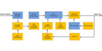
Optocouplers provide an excellent solution for low-cost, reliable isolation. However, they have several unwelcome characteristics, including limited frequency response, that can make them less suitable for use in the higher-frequency switching converters found in a growing number of applications. In response,Power Integrationshas developed aninductive-based isolation technology called FluxLink.
FluxLink is currently used in many of PI's InnoSwitch series of switched power supply ICs. These include theINN3947CQ-TLandINN3949CQ-TLth automotive-qualified开关电源集成电路at integrate a 1700-V-rated SiC MOSFET.
Intended primarily to power the low-voltage electronics in 600- and 800-V battery and fuel-cell electric vehicles, the converters’ FluxLink isolation eliminates the need for a second dc-dc converter to power the regulator circuit. Thus, they require fewer components, have fewer failure modes, and dramatically simplify qualification testing.
Click hereto read the extended review of these products, which includes additional details about these devices, and the FluxLink technology that makes them possible.
Read more articles in theThis Week in PowerBitesSeries