
AtAPEC 2019,Menlo Microwas showing off its new power relay made withmicroelectromechanical-systems(MEMS) manufacturing. Menlo Micro, a spin-off from General Electric, was looking to develop reliable, safe power switching technology for its MRI and other medical equipment.
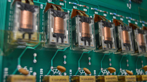
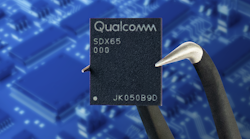
Menlo Micro first applied the GE-licensed technology to RF and other lower-power applications. Now it has designed a part that can handle 150 V and 3 A(Fig. 1). TheMM1200-6is a MEMS relay that the company claims can operate three billion times at 85°C. You operate the six switches via an SPI (serial peripheral interface) bus. Any one of the six switches can handle 1 A, but there’s a 3-A total current limit for the package.
1. Menlo Micro’s MM1200 MEMS relay is much smaller than conventional relays. (Courtesy of Menlo Micro)
The relay has a FET in parallel with the MEMS contacts. That FET can eliminate arcing of the contacts, since the control electronics inside the part turn off the FET after the contacts open. The FET turns on preceding contact closure, accounting for a fast 10-µs turn-on time—much better than a conventional MEMS switch.
A Parallel FET
Theparalleled FETis not made clear in the Menlo Micro datasheet, but you caninfer its presence. First, the datasheet claims “ac or dc voltage rating of +150 V.” The “ac” implies it’s a bipolar device, when the “+” shows it can really only handle positive voltage. To switch ac, you would use two devices back-to-back, similar to a solid-state relay (SSR) that uses two FETs back-to-back. Also, there’s a leakage current spec of 19 pA with 150 V applied to the contacts, similar to a FET, but no information on that leakage over temperature.
Using the FET to parallel the mechanical contacts is clever and can give the best of both worlds. It can also give the worst of both worlds, such as FET gate charge injection to the source, and Miller effect. You should ensure that you don’t have these problems in your application. The parts have temperature limits and come in 85°C and 100°C versions. Note that 27 of the pins in the 49-pin BGA package are for ground, so you can get the heat out of the part. The on-resistance is 500 mΩ, so a 1-A current would generate 500 mW of waste heat. As long as you keep in mind the hybrid nature of the beast, you can be sure to look at all issues that may come up.
One benefit is that the relay actuation is electrostatic, which should make it far more immune from stray magnetic fields—these can get strong enough to pull in a conventional relay, as happened to a friend’s burn-in rack. Because the contacts actuate electrostatically, you have to supply a 75-V bias voltage as well as a 5-V logic supply. The 75-V bias voltage pin only consumes 100 µA.
Note the Noise
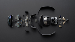
除了从场效应晶体管openi电荷注入ng and closing, the electrostatic gate is in close proximity to the contacts(Fig. 2). This means any noise in your 75-V bias supply might creep into your signal path. This should not be a problem in most applications, but still, be aware of the potential issue.
2. You close the contacts inside a Menlo Micro relay with an SPI command that applies a 75-V signal to the gate of the structure. (Courtesy of Menlo Micro)
I asked Chris Giovanniello, SVP of product development at Menlo Micro, if the hermiticity of a MEMS device helped in achieving the needed creepage and clearance distances. He replied, “Yes, it is hermetic and this is critical. We are able to stand-off relatively high voltage, 200 V or 400 V, in a very small air-gap without arcing.”
When I asked about pricing, he noted that as order volumes get into the millions, he expects to offer customers products for less than a dollar per channel, so $6 in the case of this part. Engineering samples are available and production is ramping for a Q1 2020 release; firm pricing is available now for qualified customers.
Paschen’s Law
To allow electrostatic operation, you want the contacts to be as close as possible. This might seem to be a problem for a relay rated at 150V. Giovanniello referred me toPaschen's law, which relates the gap between contacts and the arc-over voltage(Fig. 3). He noted that looking at the diagram, “You will get some hints into the physics behind what we are doing. It’s counterintuitive, but sometimes smaller air gaps can give you higher voltage without arcing.”
3. Paschen's law dictates that the arcing voltage between two contacts will increase when the contacts get closer together. (Courtesy of Wikipedia)
图中显示了击穿电压与product of pressure and air gap. The close gaps required for electrostatic actuation actually improve the voltage breakdown of the part. It’s also likely that Menlo Micro could tailor the pressure or the fill gas to achieve better breakdown voltage.
The company is not new to MEMS switches(Fig. 4). It has successful RF switches that were derived from the GE and Corning Glass processes it inherited when leaving GE. Menlo uses proprietary metal alloys that are plated onto glass wafers. The wafers, supplied by Corning, have through-glass vias (TGV) that enable the MEMS performance.
4. Menlo Micro honed its MEMS technology by first making RF switches. (Courtesy of Menlo Micro)
Giovanniello解释道,“门罗的大部分创新has been in advanced materials and processes for making high-reliability contact switches. In particular, custom alloys which are mechanically very robust for long lifetime, but also highly conductive, for low loss. We also fabricate these switches on either silicon or glass, which gives us ultra-high performance in terms of isolation and RF specs. This is a unique attribute, as there is not so much MEMS processing on glass “
Be aware that there’s a lot of research and development in high-power MEMS switches. Some researchers are investigatingmagnetic actuation, where you can generate much greater contact forces with lower applied voltages.Other researchclaims to have reached a milestone of 1000-V breakdown voltage with nearly an ampere current carrying per switch. If they can bring this into production, that would mean a truly bipolar relay with galvanic isolation between the drive pins and the contacts.
MEMS RF Switches
Most MEMS switches are intended for RF appliances, where they don’t have to carry much current(Fig. 5). Analog Devices hasan extensive line of MEMS switches, no doubt aided by their pioneering research intoMEMS accelerometers. ADI has a greatexplanation of the switch techon its website.
5. Analog Devices has a wide selection of MEMS switches targeting RF applications. The bondwire at the upper right gives an idea of the small scale of the part. (Courtesy of Analog Devices)
Even if you can’t use a MEMS device, remember you can use Menlo Micro’s trick and commutate a conventional relay with a FET, transistor, or triac. You get the same benefits—no arcing—since the active device is carrying the load when you open the contacts. You should get relay life approaching the life under no load. By applying the active device before closing the contacts, you can also improve contact life, as the contacts will not be carrying current when they bounce closed.
If you need a long life, don’t forget aboutreed relays. Developed for the telephone industry decades ago, they can offer very long lifetimes and the same hermaticity as a MEMS relay. With nearlya dozen manufacturers, you might find a part that works for you. I have become a fan of hermetic relays after a conventional onecaught firein my electric tea kettle(Fig. 6).
6. This relay burned up inside a Cuisinart tea kettle. The top is removed to view the internal damage, which was extensive. Non-hermetic relays can be a problem in wet environments.