
Download this article as a .PDF
Ongoing developments in advanced driver assistance systems (ADAS) are expanding the capabilities and affordability of vehicles that can alert and assist drivers using radar technology mostly focused over the 76-to-81 GHz spectrum.Part 1provided an overview of ADAS systems and discussed various radar systems and architectures. Part 2 discusses multi-beam and multi-range design and examines antenna design for multiple-input, multiple-output (MIMO), and beam-steering technologies for 5G that will be useful for automotive safety in the future.
Multi-Beam/Multi-Range Design
A typical adaptive-cruise-control (ACC) stop-and-go system requires multiple short- and long-range radar sensors to detect nearby vehicles. The shorter-range radar typically covers up to 60 m with an angle coverage up to ±45°, allowing the detection of the vehicle’s adjacent lanes that may cut into the current travel lane. The longer-range radar provides coverage up to 250 m and an angle of ±5° to ±10° to detect vehicles in the same lane, further ahead.
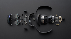
To support multiple ranges and scan angles, module manufacturers such as Bosch, DENSO, and Delphi have developed and integrated multi-range, multi-detection functionality into increasingly capable and cost-sensitive sensors using multi-channel transmitter (TX)/receiver (RX) architectures(Fig. 1)。These different ranges can be addressed with multi-beam/multi-range radar by employing radar technology such as frequency-modulated-continuous-wave (FMCW) and digital beamforming with antenna-array design.
1. Bosch的此中端雷达传感器具有三个发射器和四个接收器。它支持主天线的160m(±6°),100m(±9°)和60m(±10°)的水平视野,以及36 m(±25°)和12 m(±±±±±±±±±±±±±±±±±±±±±±±1042°)用于海拔天线。照片由系统加上咨询提供。
Antenna Design
A multi-modal radar for an ACC system1based on an FMCW radar driving multiple antenna arrays is shown inFig. 2。这个带有数字光束成型的多光束,多范围的雷达在24和77 GHz上都可以运行,使用两个开关阵列天线实现长距离,窄角覆盖范围(150 m,±10°)和宽范围,宽- 角覆盖范围(60 m,±30°)。此示例说明了多个天线阵列系统的使用,包括多个(5×12个元素)串联贴片阵列(SFPAS)用于长距离,窄角检测(77 GHz);单个SFPA(为24 GHz设计的1×12元素)用于短距离,广角检测;此类系统所需的接收器的四个(1×12)SFPA。
2. Shown is a multi-band, multi-range FMCW digital beam-forming ACC radar that utilizes six individual SFPAs.
Radar performance is greatly influenced by the antenna technology, which must consider electrical performance such as gain, beam width, range, and physical size for the particular application. The multiple, fixed TX/RX antenna arrays in the example radar were optimized for range, angle, and side-lobe suppression. A patch antenna is relatively easy to design and manufacture and will perform quite well when configured into an array, which results in an increase of overall gain and directivity.
The performance of a rectangular patch antenna design is controlled by the length, width, dielectric height, and permittivity of the antenna. The length of the single patch controls the resonant frequency, whereas the width controls the input impedance and the radiation pattern. By increasing the width, the impedance can be reduced. However, decreasing the input impedance to 50 Ω often requires a very wide patch antenna, which takes up a lot of valuable space. Larger widths can also increase the bandwidth, as does the height of the substrate.
底物的介电常数控制着较低值的边缘场,从而导致更宽的边缘,从而更好地辐射。降低介电常数也会增加天线bandwidth。The efficiency is also increased with a lower value for the permittivity.
设计一个single-patch天线或阵列possible through the use of design software that utilizes electromagnetic (EM) analysis to accurately simulate and optimize performance. NI AWR Design Environment includes AXIEM 3D planar and Analyst 3D finite-element method simulators. In addition to simulating antenna performance such as near- and far-field radiation patterns, input impedance, and surface currents, these co-simulate directly with Visual System Simulator (VSS)—automatically incorporating the antenna simulation results into the overall radar system analysis without the need to manually export/import data between EM simulator and system design tools.
Both AXIEM and Analyst take the user-defined physical attributes of the antenna such as patch width and length, as well as the dielectric properties such as material and substrate height, to produce the electrical response. AXIEM is ideal for patch-antenna analysis, whereas Analyst is best suited for 3D structures such as modeling of a coaxial feed structure or finite dielectric (when proximity to the edge of a printed-circuit-board [PCB] would impact antenna performance; seeFig. 3).
3. This figure illustrates an example of an edge-coupled single-patch antenna optimized in AXIEM for center return loss and broadside gain to design frequency.
Figure 4shows a patch-antenna array with corporate feed and 167 k unknowns solved in less than 6.5 minutes with a quad core.
4. Shown is an 8 × 16 patch-antenna array (128-element) with corporate feed (single-feed port) and 167 k unknowns (1.88 GHz) solved in approximately 6.5 minutes with quad core.
To determine the physical attributes that will yield the desired electrical response, antenna designers can use NI AWR software’s AntSyn antenna synthesis and optimization tool(图5)。AntSyn enables users to specify the electrical requirements and physical size constraints of the antenna. The software explores a set of design configurations and determines the optimum structure based on proprietary genetic optimization and EM analysis. The resulting antenna geometry can then be imported in a dedicated planar or 3D EM solver, such as AXIEM or Analyst, for verification or further analysis/optimization.
5. This figure illustrates the AntSyn antenna synthesis specification interface and library of antenna types (a) and simulated results based on user-specified antenna requirements (b).
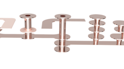
Planar elements can easily form array structures by combining very simple elements such as microstrip patches. Patches can be configured in a series such as the 1 × 8 patch array inFig. 6, where each element is connected serially by a “tunable” section of transmission line. In this AXIEM project, the lengths and widths of each array element and the connecting transmission lines were defined with variables to allow optimization of the overall array performance.
6.该软件允许使用具有参数化修饰符的串联1×8补丁阵列进行优化。
The 1 × 8 array can be further expanded into an 8 × 8 array for a high-gain fixed-beam design(Fig. 7)。This replicates the 8 × 8 element array reported in Ref. 2.
7. This is 77-GHz 8 × 8 antenna array. Parameters are N*λ/2 feeding with λ/2 < spacing < λ.
在Ni AWR设计环境中,可以使用专有的分阶段阵列模型在VSS中作为系统行为块表示数组,该模型使设计人员能够指定数组配置(元素的数量,元素间距,天线辐射模式,受损元素,增益,逐渐变细,逐渐变细,增益,增益,逐渐成分以及更多),以高级了解所需性能的数组要求,例如增益和侧叶。这种方法最适合大规模阵列(数千个要素)和系统设计师为天线阵列团队开发基本要求。
8. Shown is a 4 × 4 patch-antenna array with individual ports for each element, enabling the feed structure (lower left) to be defined and co-simulated at the circuit/system level to monitor the changing antenna input impedance per element and control beam steering through the RF feed network.
该数组也可以在Axiem中建模或使用详细的物理阵列进行建模,并指定单个端口供稿(Fig. 8)or a single feed if the feed network is also implemented in AXIEM/Analyst(图9)。
9. This figure shows the simulation1 of published 8 × 8 patch array on RO4003C PCB, approximately 2.3 × 2.5 cm. Tree-structure corporate feeding paths guarantee that the overall radiation is constructive, resulting in an array with greater than 20 dBi gain over a 1-GHz bandwidth.
This approach enables the design team to investigate the interaction between the beam angle and the input impedance of each individual element, allowing RF front-end component designers to account for impedance loading effects on transceiver performance. This capability highlights the importance of having RF circuit, system, and EM co-simulation to accurately investigate circuit/antenna behavior before fabricating these complex systems.
MIMO和光束驱动天线技术
For road vehicles, a radar will receive unwanted backscatter off the ground and any large stationary objects in the environment, such as the sides of buildings and guardrails. In addition to direct-path reflections, there are also multipath reflections between scatterers, which can be used to mitigate the impact of clutter through the use of MIMO antennas.
MIMO雷达系统使用系统em of multiple antennas, with each transmit antenna radiating an arbitrary waveform independently of the other transmitting antennas. Each receiving antenna can receive these signals. Due to the different waveforms, the echo signals can be re-assigned to the single transmitter. An antenna field of N transmitters and a field of K receivers mathematically results in a virtual field of K·N elements, resulting in an enlarged virtual aperture that allows the designer to reduce the number of necessary array elements. MIMO radar systems thereby improve spatial resolution and provide a substantially improved immunity to interference. By improving the signal-to-noise ratio, theprobability of detectionof the targets is also increased.
VSS is able to implement user-specified MIMO algorithms and evaluate the overall performance as it relates to the channel model(Fig. 10)。Users can simulate a highly-customizable multipath fading channel that includes channel path loss, the relative velocity between the transmitter and receiver, and the maximum Doppler spread. Supporting independent or continuous block-to-block operation, the channel can contain multiple paths (LOS, Rayleigh, Ricean, frequency shift) that can be individually configured in terms of their fading types, delays, relative gains, and other applicable features. This module can also simulate a receiver antenna array with user-defined geometry, enabling simulation of single-input, multiple-output (SIMO) systems.
10. VSS can implement user-specified MIMO SIMO algorithms.
Conclusion
Aside from becoming more sophisticated and reliable, ADAS systems will become more prevalent on most (if not all) vehicles in the not-too-distant future. Thanks to the similar advances in antenna-array and millimeter-wave technology that are occurring in 5G communications, most cars and trucks will be considerably safer than they are today. Advances in simulation technology—particularly in RF-aware circuit design, array modeling, and system-level co-simulation—will enable antenna designers and system integrators to optimize these systems for challenging size, cost, and reliability targets.
参考
- Rohling, Hermann; Meinecke, Marc-Michael, “Waveform Design Principles for Automotive Radar Systems,” Technical University of Hamburg-Harburg/ Germany, Conference: Radar, 2001 CIE International Conference on, Proceedings /react-text.
- -H. Jeong, H.-Y. Yu, J.-E. Lee, et. al., “A Multi-beam and Multi-range Radar with FMCW and Digital Beam-forming for Automotive Applications,”Progress in Electromagnetics Research,卷。124,285 {299,2012}。
- Jri Lee, Yi-An Li, Meng-Hsiung Hung, and Shih-Jou Huang, “A Fully-Integrated 77-GHz FMCW Radar Transceiver in 65-nm CMOS Technology,”IEEE Journal of Solid-State Circuits,卷。45,第12号,2010年12月。
Bosch Mid Range Radar (MRR) Sensor reverse engineering & costing report。